.png)
 English
  Spanish
  Japanese
  Korean
  Russian
  Chinese
PCB milling is not always the first process engineers think about when choosing a depaneling method.
But on a real production line, the question is usually more practical:
Can we separate the boards cleanly without damaging components, slowing production, or creating unnecessary costs?
That question became particularly relevant at a semiconductor electronics manufacturing site where the production team was working with different PCB outlines, relatively high-value assemblies, and frequent product changes.
Instead of looking for the fastest cutting method on paper, the team focused on something more useful: which process could remain stable when the PCB design changed?
🏭 The Production Problem Was More Than Just Cutting
The customer was producing electronic assemblies for semiconductor-related equipment.
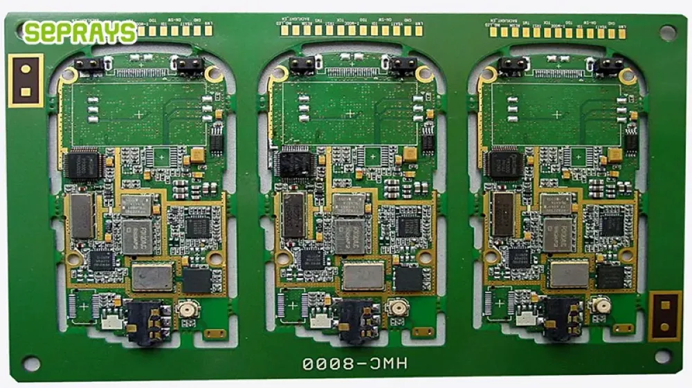
The PCB panels were not all simple rectangles. Some included curves, irregular outlines, and routed tabs. Component density was also increasing around the board edges.
The previous separation process created several practical concerns:
- Different PCB designs required different handling methods.
- Manual separation introduced operator-dependent variation.
- Mechanical stress had to be controlled around sensitive components.
- Cutting debris needed to be managed.
- Tool wear could gradually affect edge quality.
- Frequent product changes made dedicated tooling less attractive.
This is where a programmable milling process became worth evaluating.
A router-based process can follow different programmed contours without requiring a new die for every PCB design. That flexibility is one of its main advantages for high-mix production.
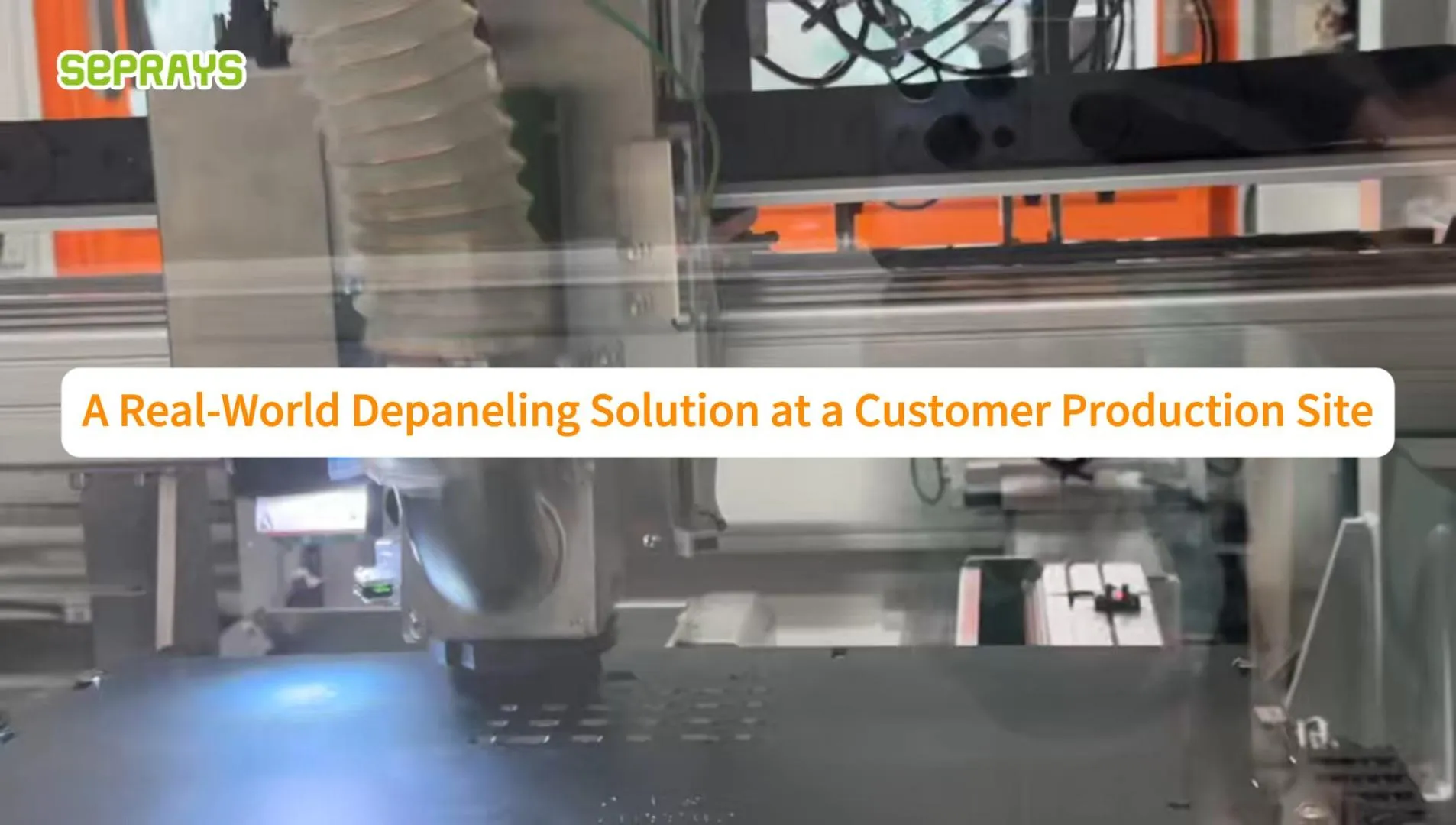
⚙️ What the Milling Process Looks Like on the Factory Floor
The actual process is relatively straightforward.
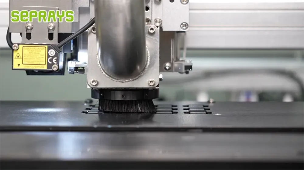
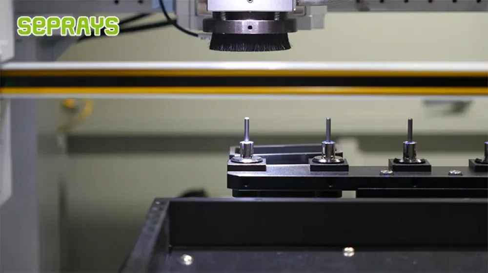
First, the panel is loaded onto the working area and positioned against the fixture.
The machine then identifies the programmed reference points before starting the cutting path.
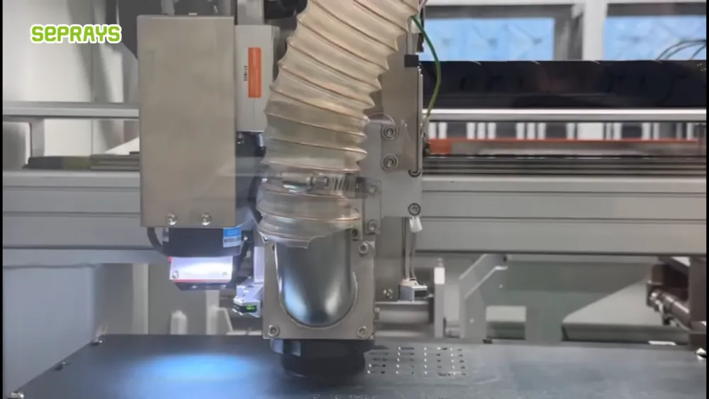
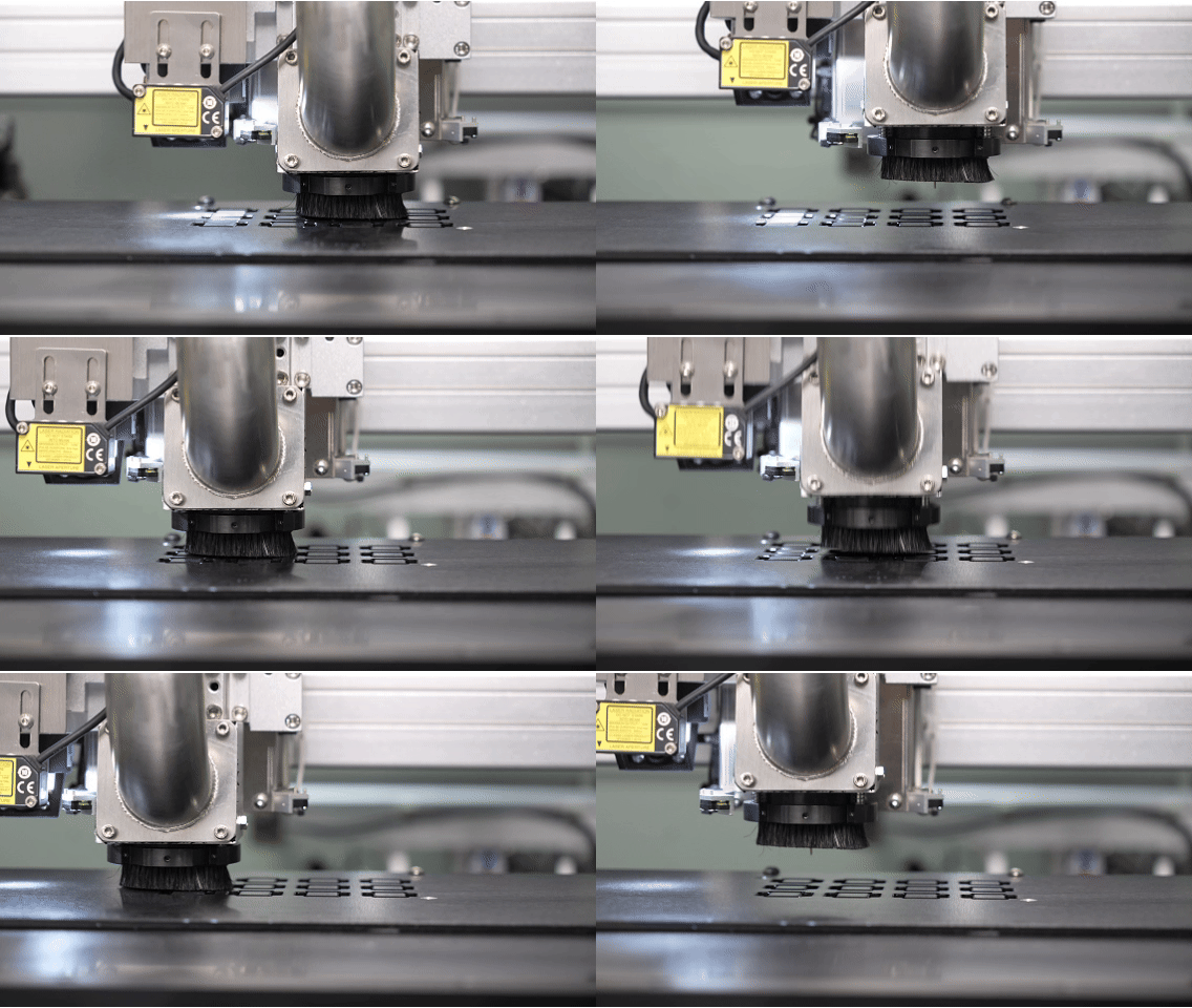
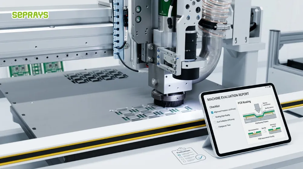
Instead of forcing the panel apart, the milling cutter follows the predefined PCB outline and removes material along the route.
For the customer, the important part was not simply cutting speed.
It was repeatability.
The production team wanted the same program to produce a predictable result after multiple panels, while keeping the board properly supported during cutting.
That is especially important when working with dense PCB assemblies. Recent industry guidance also emphasizes that routing quality depends on the combination of fixture support, tool condition, cutting path, and process parameters—not spindle speed alone.
🧩 Why Milling Made Sense for This Application
There is a common assumption that the fastest depaneling process is automatically the most economical.
In practice, that is not always true.
Consider three different production situations:
| Production Situation | Suitable Method | Main Reason |
|---|---|---|
| Simple rectangular PCB, straight separation | V-Cut | Fast and economical |
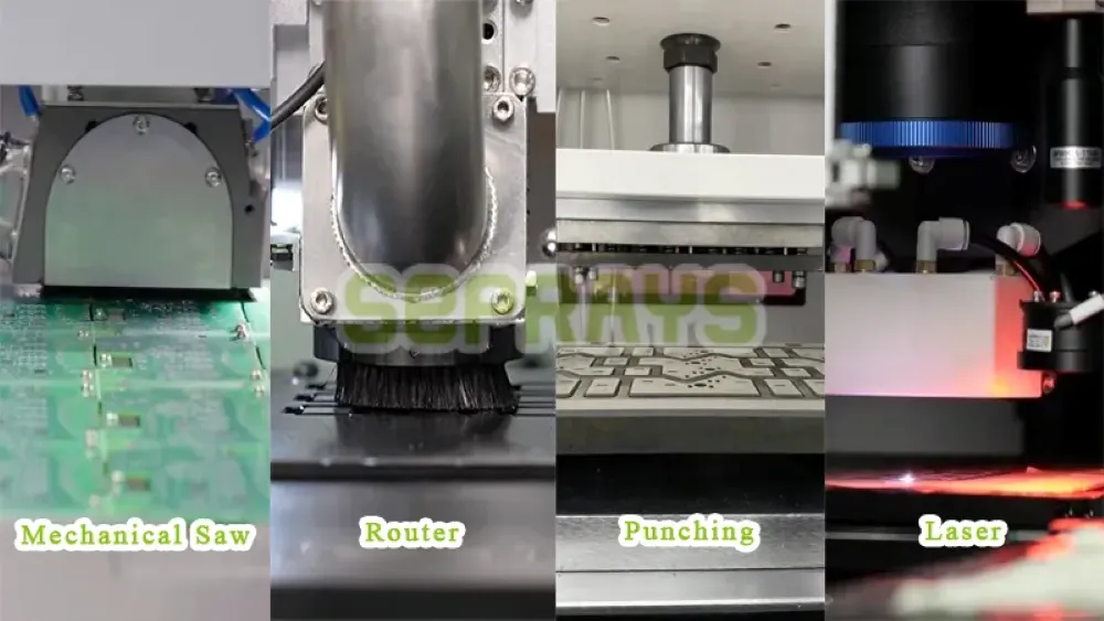
| Complex outline, multiple PCB designs | Milling / Router | Flexible cutting path |
| Very low mechanical contact required | Laser | Non-contact cutting |
| Extremely stable, high-volume geometry | Punching | Fast repeated cycles |
| Straight-line separation | Sawing | Efficient linear cutting |
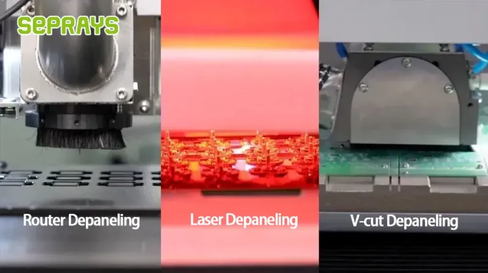
V-Cut can be extremely efficient when the PCB design allows it. Punching can also become attractive when production volume is very high and the product design remains stable.
But those advantages become less obvious when PCB designs change frequently.
That was one of the important lessons from this customer project.
The best depaneling process is not necessarily the fastest machine. It is the process that fits the product mix.
💰 Looking at the Cost Beyond Machine Price
When factories compare depaneling equipment, the machine quotation is often the easiest number to compare.
It is not necessarily the most important one.
A more realistic calculation should include:
Equipment + tooling + cutters + labor + maintenance + cleaning + scrap + changeover time
For example, a low-cost separation process may become more expensive if it requires significant manual handling.
A high-speed process may also lose its advantage if a new PCB design requires expensive tooling.
For a high-mix production environment, programmable routing can reduce the need for dedicated tooling and make product changeovers easier. Industry comparisons generally identify routing as particularly suitable for irregular outlines and frequent design changes.
The surprising part?
A slightly slower process can sometimes produce a lower total production cost.
That happens when it reduces rework, tooling changes, operator intervention, or damaged boards.
🧹 The Dust Problem Should Not Be Ignored
There is one area where mechanical milling clearly requires attention: dust.
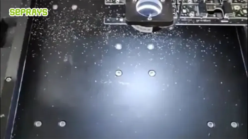
FR-4 and other PCB materials generate particles during mechanical cutting. A proper extraction system is therefore part of the process, not simply an optional accessory.
The customer specifically checked:
- Dust collection performance
- Suction position
- Fixture airflow
- Filter condition
- Cutter condition
- Cleaning frequency
A common mistake is to assume that a larger dust collector automatically solves the problem.
In reality, dust capture depends on where particles are generated and how effectively they are captured at the cutting point. Recent industry analysis highlights factors such as suction distance, airflow resistance, filter loading, and tool wear.
So the practical solution is not simply “add more suction.”
It is to design the cutting and extraction process together.
🔍 What We Learned From the Customer Application
During the evaluation, several points became clear.
1. Fixture design matters
Even a precise machine cannot compensate for poor PCB support.
The panel needs to remain stable during cutting. For different PCB designs, the fixture configuration may need to change.
2. Cutter condition affects the result
A worn milling cutter can gradually change edge quality and increase debris.
The solution is not to wait until the edge becomes visibly poor.
Tool life should be monitored as part of routine production management.
3. Cutting speed is a balance
Increasing feed speed may improve theoretical throughput.
But pushing the process too far can increase burrs, vibration, tool wear, or edge damage.
A stable process window is usually more valuable than chasing the maximum feed rate.
4. PCB design should be considered early
Depaneling should not be treated as an afterthought.
Component location, board thickness, tabs, edge clearance, and panel design all influence the final separation process.
Research and industry experience both show that PCB design and the depaneling method should be considered together rather than independently.
📊 Milling vs. Other Depaneling Methods
| Factor | Milling | V-Cut | Laser | Punching |
|---|---|---|---|---|
| Irregular outlines | Excellent | Limited | Excellent | Limited |
| Straight cuts | Good | Excellent | Good | Good |
| Mechanical contact | Yes | Yes | No | Yes |
| Tooling flexibility | High | High | High | Low |
| Dust | Requires extraction | Low | Requires fume control | Low |
| High-mix production | Excellent | Moderate | Excellent | Poor |
| Stable mass production | Good | Excellent | Good | Excellent |
| Product changes | Easy | Easy | Easy | Expensive |
| Initial investment | Moderate | Moderate | Higher | Moderate + tooling |
These are general process tendencies, not universal specifications. Actual performance depends on PCB material, thickness, component layout, fixture design, cutting parameters, production volume, and quality requirements.
🧠 An Unexpected Conclusion: Faster Is Not Always Better
After looking at the production process as a whole, the customer did not simply ask:
“How many boards can we cut per hour?”
The better question was:
“How many good boards can we produce consistently?”
That difference matters.
If a faster process creates more manual inspection, more cleaning, more tool changes, or even a small increase in damaged boards, the apparent productivity advantage can disappear.
For high-value semiconductor and electronics assemblies, avoiding a small number of expensive failures may be more important than saving a few seconds per panel.
This is why depaneling should be evaluated using total process cost and yield, rather than machine cycle time alone.
🌎 A Seprays Group Customer Application
In this type of application, Seprays Group worked with the customer from the PCB process perspective rather than simply matching a machine to a specification sheet.
The team considered the PCB outline, production mix, cutting requirements, fixture support, dust extraction, and future product changes before selecting the configuration.
With more than 30 years of experience in PCB/FPC depaneling, Seprays Group has developed solutions for different production environments, from standalone equipment to automated depaneling systems.
The objective is simple:
Build a process that works reliably in the customer’s factory—not just a machine that performs well in a demonstration.

🛠️ When Should You Consider Milling?
Milling is worth considering when:
- PCB outlines are irregular or curved.
- Several PCB models run on the same production line.
- Product changes are relatively frequent.
- Dedicated punching dies are difficult to justify.
- Clean and controlled board separation is required.
- The production team wants programmable cutting paths.
- Mechanical stress needs to be controlled, but laser processing is not necessary.
It may not be the best choice for every application.
- For simple, high-volume rectangular PCBs, V-Cut can remain more economical.
- For extremely sensitive or thin assemblies where mechanical contact is a major concern, a laser may be a better fit.
- For very high-volume products with stable geometry, punching may eventually offer the lowest cost per unit.
The right answer depends on the PCB—not the machine category.
📌 What We Would Check Before Choosing a Machine
If we were evaluating a new depaneling process today, these would be the first questions:
- What is the PCB material and thickness?
- What are the actual board dimensions?
- Are the outlines straight, curved, or irregular?
- How close are components to the cutting path?
- How many PCB models will share the equipment?
- What is the monthly production volume?
- How often will the product change?
- What edge quality is acceptable?
- How will dust or process residue be controlled?
- What is the real cost of a rejected board?
A short production trial can often answer these questions more reliably than a long equipment comparison.
🏆 Why Choose Seprays Group?
Seprays Group has been dedicated to PCB/FPC depaneling technology for more than 30 years, providing a full range of solutions—from milling-cutter depanelers, laser depanelers, V-groove depanelers, and punching depanelers to automated PCB handling systems.
Our equipment has been used and trusted by leading manufacturers, including Foxconn, Flextronics, State Grid, Luxshare, Compal, Wistron, China Electronics, Quanta, CRRC, China Aerospace, OPPO, ZTE, and Bosch. These solutions are deployed across manufacturing facilities in China and international markets.
What matters to us is not simply supplying a depaneling machine.
It is about understanding how the PCB is produced, where the current process creates problems, and what may change as production develops.
For a new project, the most useful starting point is often the PCB itself.
Share the PCB drawing, Gerber files, panel layout, production volume, or current separation process, and the appropriate depaneling method can be evaluated from the actual application.
If you have a similar production challenge, feel free to contact us.
WhatsApp: +8618929266433
E-mail: sales@seprays.com
❓ FAQ
1. Is milling suitable for complex PCB shapes?
Yes. Milling is particularly useful for irregular, curved, or mixed PCB outlines because the cutting path can be programmed according to the board geometry.
2. Does PCB milling create dust?
Yes. Mechanical milling generates PCB cutting debris, so an appropriate dust extraction system should be included in the production process.
3. Is milling cheaper than laser depaneling?
Not necessarily. Milling generally has a lower equipment entry cost, but the better choice depends on PCB material, tolerance, production volume, component sensitivity, cleaning requirements, and total process cost.
4. When is V-Cut a better choice than milling?
V-Cut can be a better option for high-volume rectangular PCBs with straight separation lines. It becomes less suitable when the PCB requires complex contours or greater design flexibility.
5. How should I choose between milling and laser depaneling?
Start with the PCB rather than the machine. Consider board thickness, material, outline complexity, component clearance, required precision, production volume, cleanliness requirements, and acceptable mechanical stress. A sample test using the actual PCB is often the most reliable way to make the final decision.