.png)
 Chinese
  English
  Spanish
  Japanese
  Korean
  Russian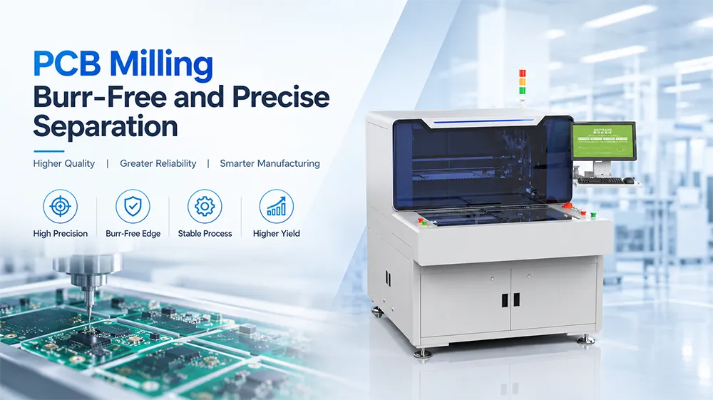
PCB milling sounds straightforward: a rotating cutter follows a programmed path and separates individual boards from a panel. In production, however, getting a clean edge is not simply a matter of increasing spindle speed.
The real challenge is controlling cutting force, tool condition, positioning, support, dust, and board movement at the same time.
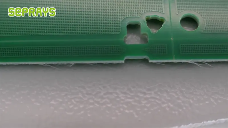
A board can look acceptable after separation but still have small burrs, dimensional variation, lifted traces, or stress around sensitive components. These problems often become expensive later, especially when the PCB enters final assembly.
So, what actually makes a milled PCB edge clean and repeatable?
🔍 Why Do Burrs Appear During PCB Separation?
Burrs usually come from an unstable cutting process rather than a single machine setting.
Common causes include:
- Worn or unsuitable milling cutters
- Incorrect spindle speed
- Excessive cutting speed
- Poor PCB support
- Panel movement during cutting
- Incorrect cutting depth
- Misalignment between the programmed path and the actual panel
- Dust accumulation around the cutting area
Tool wear deserves particular attention.
As a cutter becomes dull, cutting resistance can increase. The result may be a rougher edge, more debris, dimensional variation, or even tool breakage. Tool condition and cutting parameters therefore need to be managed together rather than treated as separate issues.
Practical lesson: a faster cutter does not automatically produce a cleaner PCB.
⚙️ How Does the Milling Process Stay Precise?
A stable process normally depends on four factors working together.
1. High-speed spindle
A high-speed spindle allows the machine to use small-diameter cutters while maintaining controlled cutting conditions.
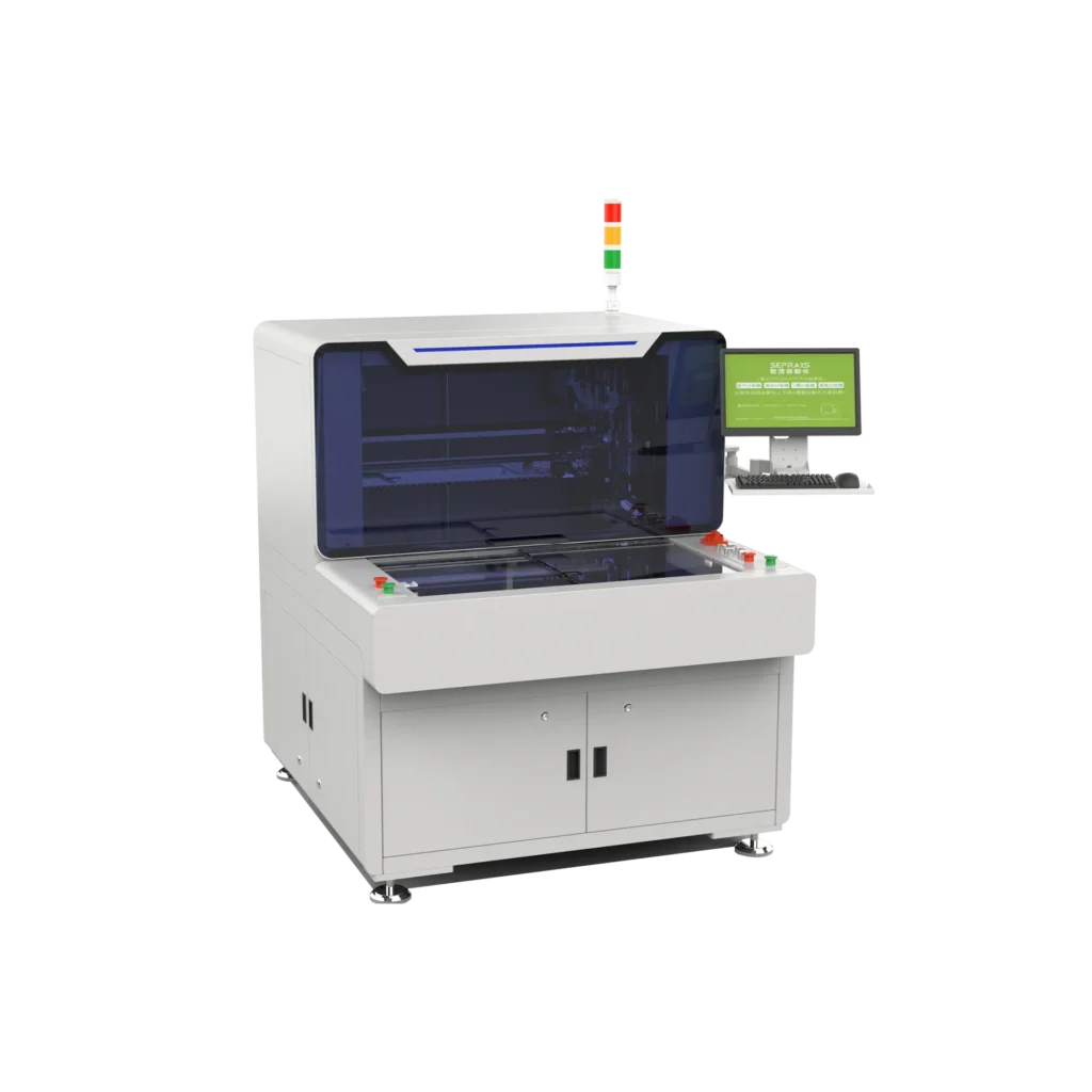
For example, Seprays’ ZM300N supports spindle speeds up to 100,000 rpm and cutter diameters from 0.8–3.0 mm. Its cutting speed can be adjusted from 1–100 mm/s.
The important point is not the maximum number itself.
The machine needs to maintain the appropriate relationship between RPM, feed rate, cutter diameter, material, and cutting depth.
2. Stable positioning
Even an accurate CNC system cannot compensate for a PCB that moves during cutting.
Dedicated fixtures help hold the panel in position. CCD vision can then detect the actual board position and correct the cutting path before processing. The ZM300N combines dedicated jigs with CCD color vision alignment for this purpose.
3. Low mechanical stress
High-density PCBAs can contain components surprisingly close to the separation contour.
The objective is therefore not simply:
Cut the board quickly.
It is:
Remove the unwanted material without transferring unnecessary force to the finished PCBA.
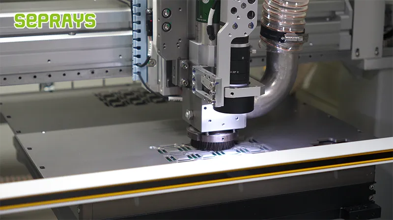
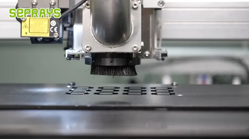
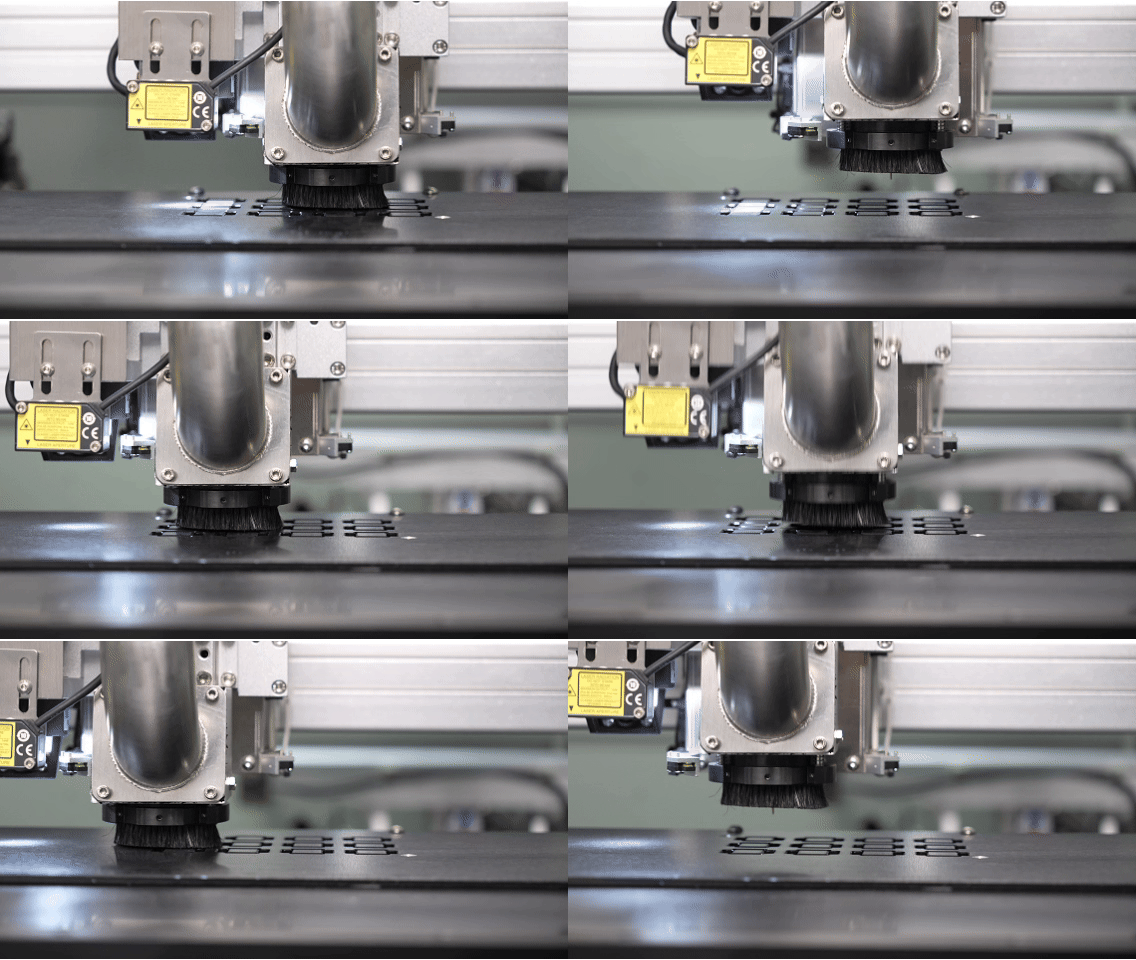
The ZM300N uses a floating-brush design to reduce Z-axis stress, together with an ESD-safe spindle and anti-static components.
4. Consistent motion
The cutting path should remain stable from the first panel to the hundredth.
The ZM300N specifies ±0.05 mm cutting accuracy and ±0.01 mm repeatability, with AC servo-driven XYZ motion.
These numbers are useful, but they should still be verified against the actual PCB design. Machine accuracy and finished-board tolerance are not exactly the same thing.
🧹 Where Does Dust Control Fit In?
Dust is easy to underestimate.
Milling produces fine PCB particles that can settle around the machine, fixtures, and components. In a production environment, poor extraction can turn a cutting-quality problem into a maintenance problem.
A practical system should consider:
- Cutting dust direction
- Upper or lower extraction
- Negative-pressure monitoring
- Fixture cleanliness
- Cutter wear
- Cleaning frequency
The ZM300N supports upper or lower external dust collection, negative-pressure detection, and an ionizing air gun for dust removal.
This is especially relevant for factories running continuously rather than processing a few panels per day.
📊 Milling vs. Other PCB Separation Methods
There is no universal “best” depaneling technology.
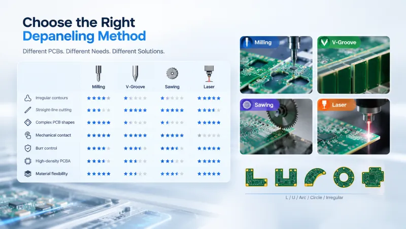
| Requirement | Milling | V-Groove | Sawing | Laser |
|---|---|---|---|---|
| Irregular contours | Excellent | Limited | Limited | Excellent |
| Straight-line cutting | Good | Excellent | Excellent | Good |
| Complex PCB shapes | Excellent | Poor | Limited | Excellent |
| Mechanical contact | 有 | 有 | 有 | No |
| Burr control | Good with correct parameters | Generally clean | Good | Excellent |
| High-density PCBA | Suitable with proper support | Depends on design | Depends on design | Excellent |
| Material flexibility | High | Requires suitable scoring | High | Very high |
Milling is particularly useful when the PCB outline contains L-shapes, U-shapes, arcs, circles, or other irregular contours. Industry depaneling systems commonly use routing for complex shapes because the cutter can follow a programmed contour.
But there is an important boundary condition.
If the panel was specifically designed for V-groove separation, a V-groove solution may be simpler and faster. If the substrate is extremely sensitive or requires contactless processing, a laser may be a better fit.
The counterintuitive conclusion: choosing the most precise machine is not always the most economical decision. Choosing the right process for the PCB design usually matters more.
💰 What Does Burr-Free Separation Really Cost?
A clean edge has a cost, but a defective edge can cost much more.
Consider a simplified production calculation:
Cost per good board = (machine + labor + tooling + maintenance + downtime + scrap) ÷ good boards produced
Imagine a semiconductor electronics factory processes 10,000 panels per month.
A cheaper cutting process may reduce equipment investment, but if it causes only a small increase in:
- rework,
- cutter replacement,
- cleaning,
- board rejection,
- operator intervention,
The monthly difference can quickly become meaningful.
For example, if a factory reduces the effective scrap/rework rate from 1.0% to 0.4% on high-value assemblies, the savings may be more significant than a small difference in machine purchase price.
The exact result depends on the PCB value, labor rate, cycle time, and actual defect cost.
That is why an ROI calculation should use production data from the customer’s own boards, rather than relying only on machine specifications.
🏭 An Illustrative Semiconductor Production Case
Consider an overseas semiconductor electronics manufacturer producing compact controller boards for industrial equipment.
The company initially uses manual panel separation after SMT assembly.
The problems are familiar:
- Operators need to align every panel.
- Different operators produce slightly different results.
- Burrs occasionally require secondary inspection.
- Cutting dust increases cleaning work.
- Irregular board contours make simple blade separation unsuitable.
The factory evaluates an offline milling solution.
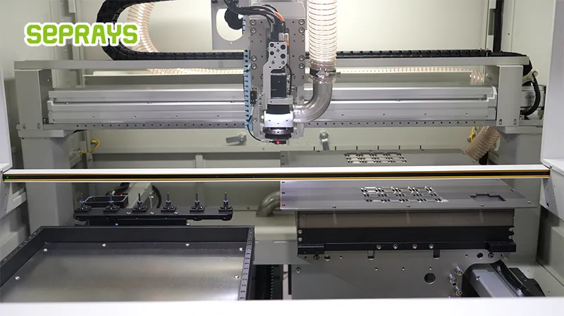
A machine such as the Seprays ZM300N can combine CCD vision alignment, dual worktables, automatic tool change, tool-break detection, and dust extraction. Its dual-table structure allows one table to be processed while the other can be prepared, reducing waiting associated with loading and unloading.
The key improvement is not simply “automation.”
It is process consistency.
The factory can establish cutting recipes, monitor tool condition, and standardize the separation process instead of relying heavily on operator technique.
This example is illustrative rather than a claim of a specific Seprays customer result. Actual gains should be validated through a production trial.
🛠️ How to Improve Separation Quality Before Buying a Machine
Before choosing equipment, collect several real production samples.
Check:
- PCB material and thickness
- Panel dimensions
- Contour geometry
- Smallest internal radius
- Component distance from the cutting path
- Required edge tolerance
- Expected monthly volume
- Current burr and scrap rate
- Dust-control requirements
- Required cycle time
Then run a sample test.
Do not only inspect the first board.
Run enough cycles to see whether the edge remains consistent as the cutter wears and the machine continues operating.
This is where production testing becomes more valuable than a specification sheet.
🌎 Why Choose Seprays Group?
Seprays Group has been dedicated to PCB/FPC depaneling technology for more than 30 years, since its establishment in Taiwan in 1993. The company provides milling-cutter depanelers, laser depanelers, V-groove depanelers, punching depanelers, and automated loading, unloading, and handling systems.
Its equipment and solutions are trusted by leading manufacturers including Foxconn, Flextronics, State Grid, Luxshare, Compal, Wistron, China Electronics, Quanta, CRRC, China Aerospace, OPPO, ZTE, and Bosch, with depaneling solutions used in factories across China and international markets.
For applications requiring high-precision contour cutting, the ZM300N combines high-speed spindle technology, CCD vision alignment, dual worktables, automatic tool change, tool detection, low-stress protection, and dust-management functions.
The better approach is to start with the PCB—not the machine.
Define the edge requirement, stress sensitivity, contour, production volume, and acceptable cost per good board first. Then select the separation technology.
If you need help evaluating a PCB milling application or comparing suitable depaneling methods, please get in touch with Seprays Group for a production-based assessment.
WhatsApp: +8618929266433
❓ FAQ
1. Can milling completely eliminate PCB burrs?
No process should promise zero burrs for every material and condition. Proper cutter selection, spindle speed, feed rate, support, and tool maintenance can significantly reduce burr formation.
2. Is milling suitable for irregular PCB shapes?
Yes. Routing is particularly useful for L-shaped, U-shaped, circular, arc, and other complex contours because the cutter can follow a programmed path.
3. Does higher spindle speed always improve cutting quality?
No. Spindle speed must match cutter diameter, feed rate, material, and cutting depth. Excessive speed without the correct process parameters can increase heat, wear, or cutting instability.
4. How can I reduce PCB damage during separation?
Use appropriate fixtures, stable positioning, vision correction, suitable cutting parameters, and low-stress support. Component location near the cutting contour should also be considered during process selection.
5. When should a factory choose milling instead of V-groove or laser?
Choose milling when flexible contour cutting and controlled mechanical separation are important. V-groove can be more efficient for suitable pre-scored straight-line panels, while laser is attractive for delicate or highly intricate applications. The right choice depends on the actual PCB design and production requirements.