.png)
 Spanish
  English
  Japanese
  Korean
  Russian
  Chinese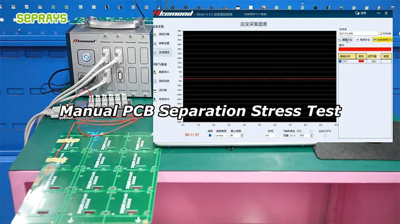
Manual PCB Separation Stress Test is a practical way to understand how much mechanical stress a PCB assembly can tolerate before choosing a production depaneling method.
For engineers, the question is rarely just “Can this PCB be separated?” A better question is: What happens to the board and its components during separation, and can the same result be repeated thousands of times?
This matters even more for high-density PCBA used in automotive electronics, medical devices, industrial controls, communication equipment, and semiconductor-related systems.
🔍 Why Perform a Separation Stress Test?
A PCB can look perfectly normal after separation while still having problems that are difficult to see immediately.
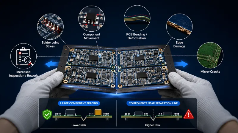
Potential risks include:
- Solder joint stress
- Component movement
- PCB bending or deformation
- Edge damage
- Micro-cracks
- Increased inspection or rework requirements
A useful test should therefore examine the complete assembly, not only the cut edge.
For example, a board with large component spacing may tolerate manual breaking or V-groove separation. The same method may become unsuitable when large components are positioned close to the separation line.
The key variable is often where the stress goes, not simply how much force is applied.
🧪 How to Conduct a Practical Manual Stress Test
A simple engineering test can provide useful information before investing in equipment.
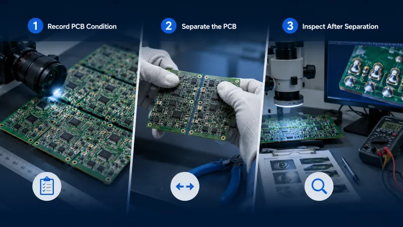
Step 1: Record the PCB Condition
Document the board before separation.
Check:
- PCB thickness
- Panel structure
- Component locations
- V-grooves or tabs
- Sensitive components near separation paths
Taking close-up photographs can make later comparison easier.
Step 2: Separate the PCB Using the Current Method
Use the same method operators normally use in production.
Do not immediately test only the easiest boards.
Include representative products and, where possible, the most difficult panel design.
Record:
- Separation force or operator feedback
- Visible board movement
- Cracking or edge damage
- Component movement
- Time required per panel
Step 3: Inspect After Separation
Visual inspection is only the first step.
For higher-value assemblies, manufacturers may combine visual inspection with electrical testing, microscope inspection, solder-joint inspection, or other established quality-control methods.
The purpose is to identify whether separation introduces defects that were not present before processing.
⚠️ What Results Should Engineers Look For?
A common mistake is to focus only on whether the PCB breaks cleanly.
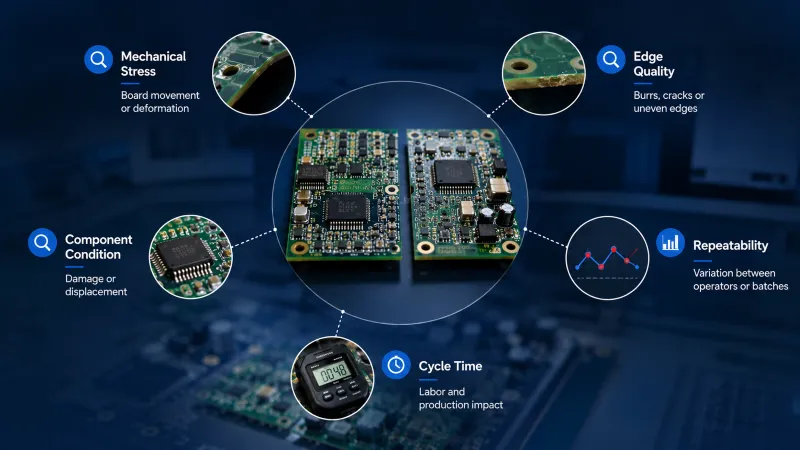
A better evaluation considers several factors:
| Test Factor | What to Observe |
|---|---|
| Mechanical stress | Board movement or deformation |
| Edge quality | Burrs, cracks, or uneven edges |
| Component condition | Damage or displacement |
| Repeatability | Variation between operators or batches |
| Cycle time | Labor and production impact |
A process that produces one excellent sample may still be unsuitable for mass production if results vary from operator to operator.
This is especially important when production volume reaches thousands or tens of thousands of assemblies.
⚙️ When Should You Move Beyond Manual Separation?
Manual testing is useful for evaluation, but it has clear boundaries.
It may be reasonable for prototypes, engineering samples, or very low-volume products.
It becomes less attractive when manufacturers face:
- High monthly production volume
- Expensive components
- Tight quality requirements
- Frequent product changes
- Increasing labor costs
- Need for repeatable processing
At this stage, the goal should not necessarily be the fastest cutting method.
A more useful target is controlled and repeatable separation.
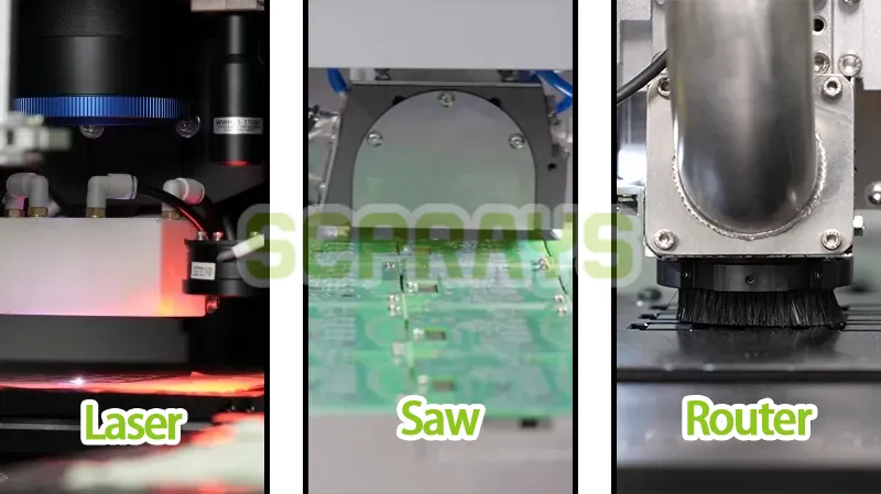
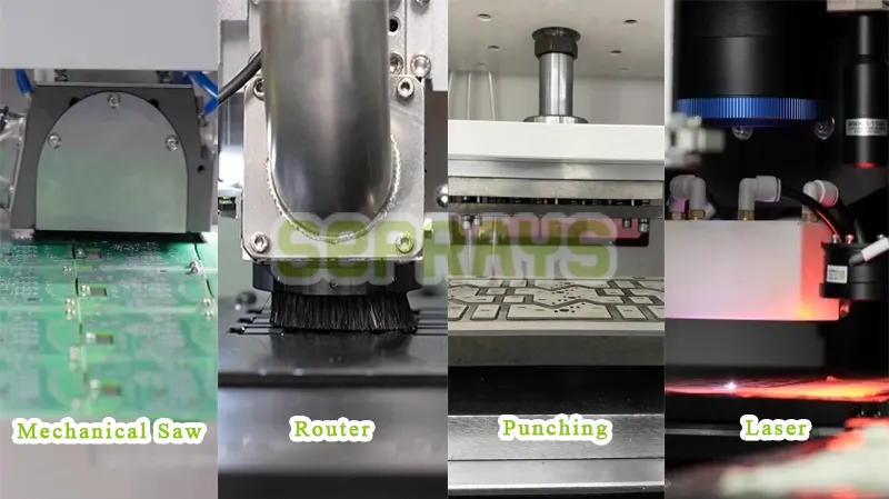
Depending on the PCB structure, engineers may compare V-groove separation, saw blade cutting, router-based depaneling, laser processing, or automated separation systems.
📊 Comparing Common Separation Methods
| Method | Main Strength | Typical Limitation |
| Manual separation | Low initial cost | High operator variation |
| V-groove | Simple and economical | Limited design flexibility |
| Saw blade | Good for straight cuts | Mechanical stress |
| Router | Flexible and precise | Requires controlled positioning |
| Laser | Very low mechanical stress | Higher investment |
| Automated system | Repeatable production | Requires process planning |
There is no universal winner.
A sensitive flexible board may require a different solution from a rigid automotive control board. Production volume, component location, panel design, and acceptable process variation should all be considered.
💰 The Cost of Ignoring Separation Stress
The visible machine cost is usually easy to calculate.
The hidden cost is harder.
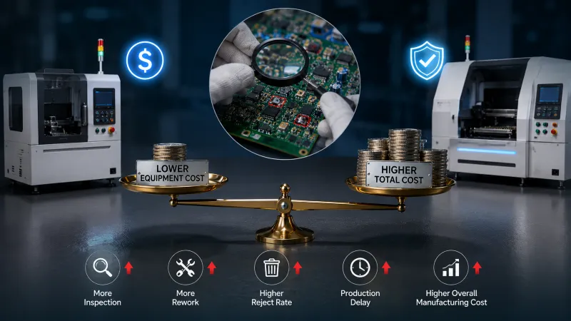
Suppose a manufacturer produces 20,000 assemblies per month. If an unstable separation process creates even a small increase in inspection, rework, or rejected boards, the financial impact can exceed the difference between two machines.
This is why a stress test should be connected to actual production economics.
Lower equipment cost does not always mean lower manufacturing cost.
Sometimes preventing one recurring quality problem is worth more than saving a few seconds of cycle time.
🏭 An Example from Overseas Electronics Manufacturing
Consider an overseas semiconductor equipment manufacturer producing controller boards with dense components positioned close to the panel separation area.
During prototype production, manual separation appeared acceptable.
After volume increased, engineers noticed inconsistent edge conditions and additional inspection work. Instead of immediately increasing production speed, the team repeated the separation evaluation and compared several processing methods.
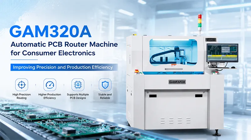
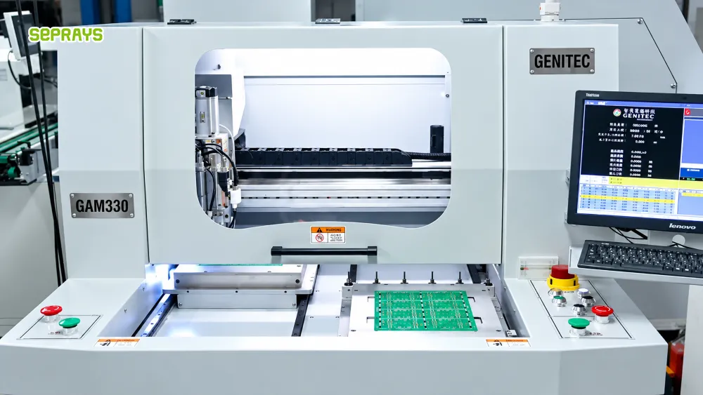
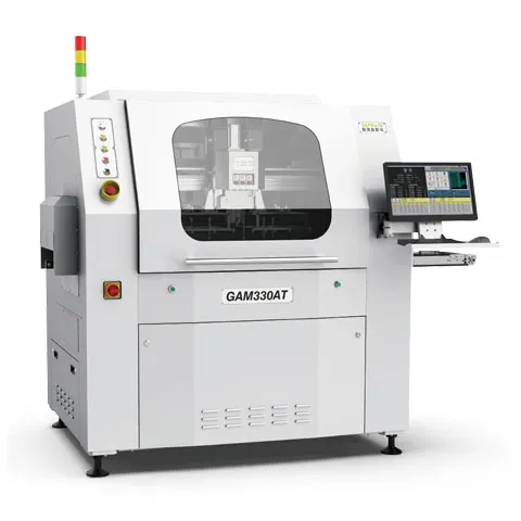
In a representative project, a Seprays depaneling solution was evaluated as part of the process review. The focus was not simply on cutting speed. Engineers looked at positioning stability, repeatability, operator involvement, and the effect on downstream inspection.
The practical lesson was straightforward:
Test the separation process before scaling the production volume.
The exact machine should be selected only after the PCB structure and production requirements are understood.
🧠 A Practical Decision Rule for Engineers
Before selecting equipment, ask five questions:
- Where is the most sensitive component?
- How close is it to the separation path?
- What stress does the current process introduce?
- Can the result be repeated across different operators?
- What happens when production volume increases?
If the current method performs well under all five conditions, an equipment upgrade may not be urgent.
If several answers are uncertain, a controlled depaneling trial is usually a better starting point than choosing equipment based only on specifications.
🌍 Why Choose Seprays Group?
With more than 30 years of experience, Seprays Group has focused on PCB/FPC depaneling technology and manufacturing solutions.
Seprays Group provides a broad range of equipment, including milling-cutter depanelers, laser depanelers, V-groove depanelers, punching depanelers, and automated handling systems. Its equipment has been used by and supplied to leading manufacturers including Foxconn, Flextronics, State Grid, Luxshare, Compal, Wistron, China Electronics, Quanta, CRRC, China Aerospace, OPPO, ZTE, and Bosch, with installations across China and international markets.
For manufacturers evaluating a new separation process, the practical value is not simply having more machine options. It is being able to compare the technology with the actual PCB structure, production volume, component sensitivity, and automation requirements.
If you are dealing with PCB separation stress, edge damage, inconsistent results, or increasing manual handling, contact Seprays Group to discuss your PCB application and evaluate a suitable depaneling approach.
WhatsApp: +8618929266433
Correo electrónico: sales@seprays.com
❓ FAQ
1. What is a PCB separation stress test?
It is a controlled evaluation used to understand how a separation method affects the PCB, components, solder joints, and finished assembly.
2. Is manual PCB separation suitable for mass production?
It can work for low-volume or prototype production, but operator variation and labor requirements can become significant as production volume increases.
3. Which PCB separation method creates the least mechanical stress?
Laser processing generally introduces very low mechanical stress, but it is not automatically the best choice. PCB structure, material, cutting requirements, production volume, and investment should also be considered.
4. How can manufacturers identify separation-related damage?
Visual inspection is a starting point. For critical assemblies, manufacturers can combine it with microscope inspection, electrical testing, solder-joint inspection, or other existing quality-control methods.
5. Should I choose a machine based on cutting speed?
Not necessarily. For high-value PCBA, repeatability, positioning stability, product protection, labor requirements, and total production cost can be more important than maximum cutting speed.