.png)
 Russian
  English
  Spanish
  Japanese
  Korean
  Chinese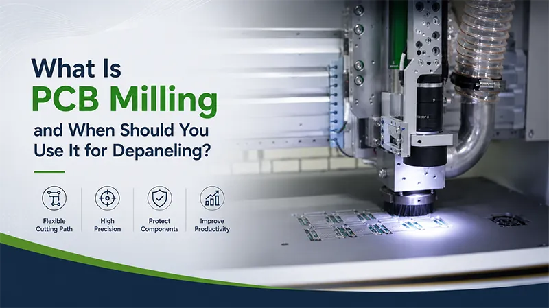
PCB milling is one of those processes that look simple until the PCB becomes more complex.
The basic idea is straightforward: a high-speed rotating cutter follows a programmed path and separates individual boards from a larger panel. But once components move close to the edge, board shapes become irregular, or production volumes increase, the choice of depaneling method becomes much more important.
For many manufacturers, the real question is not simply “Can milling cut this PCB?”
It is:
“Will milling give us the right balance of accuracy, board protection, flexibility, and production cost?”
🔍 What Is PCB Milling?
PCB milling uses a rotating cutting tool to remove material along a defined path.
Unlike V-groove separation, it does not require the PCB to follow a straight pre-scored line. The cutting path can be programmed according to the board outline.
That makes the process particularly useful for:
- Irregular PCB shapes
- Curved outlines
- Internal cutouts
- Small tabs
- High-density PCBs
- Multi-layer boards
- Boards with components positioned near the edge
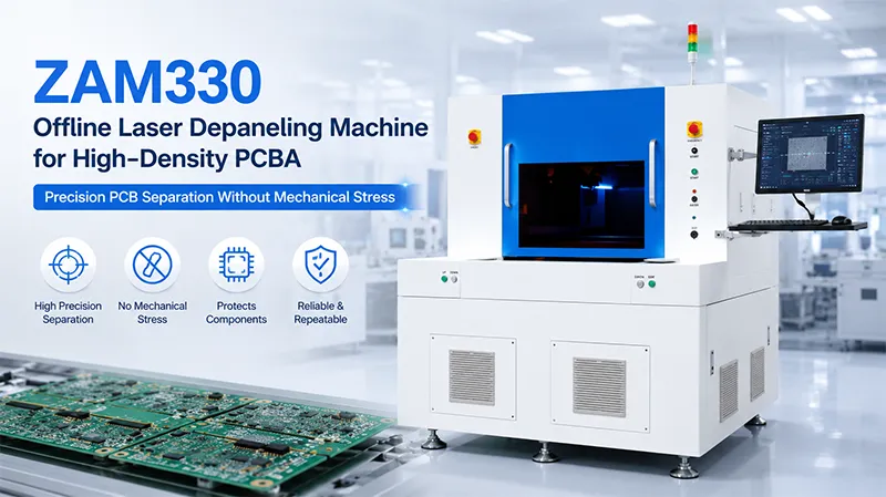
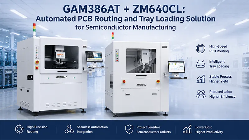
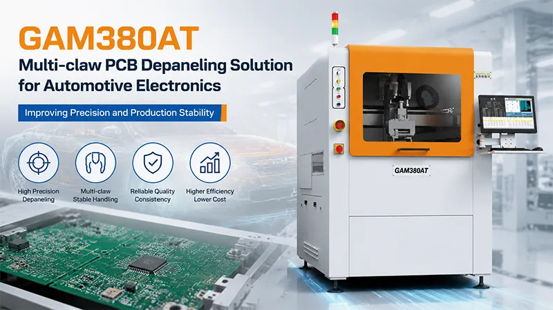
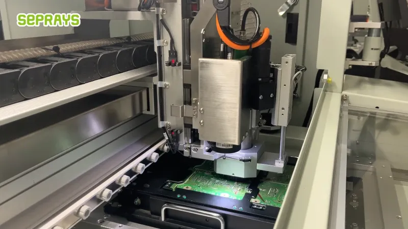
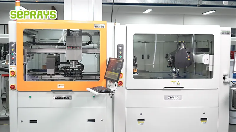
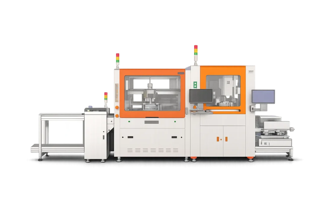
Modern milling systems can also combine positioning, dust extraction, vision alignment, automatic tool changing, and material handling. Seprays, for example, offers both offline and in-line routing systems for different production requirements.
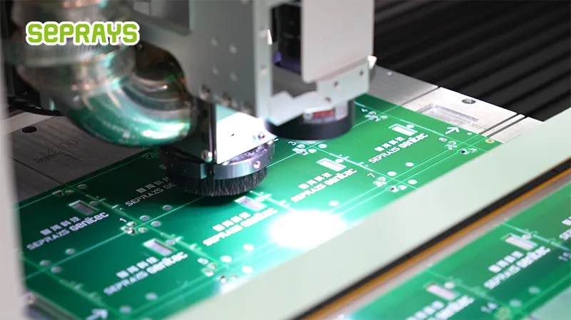
⚙️ How Does the Milling Process Work?
A typical production cycle looks like this:
Panel loading → PCB positioning → cutting-path recognition → milling → dust collection → board unloading
The cutter follows a programmed route instead of breaking the panel through mechanical force.
This distinction matters.
With a complex PCB, the manufacturer can define the exact contour instead of redesigning the panel around a straight separation line.
The actual result still depends on the PCB material, thickness, tool selection, spindle condition, cutting parameters, and fixture design.
That is why a sample test is more useful than relying on machine specifications alone.
📐 When Does Milling Make More Sense?
Milling is generally worth considering when the PCB design makes simple separation methods difficult.
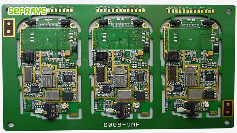
For example, imagine a semiconductor control board with several internal openings and components placed close to the outer contour.
A V-groove process may not provide enough design freedom.
Punching may require dedicated tooling.
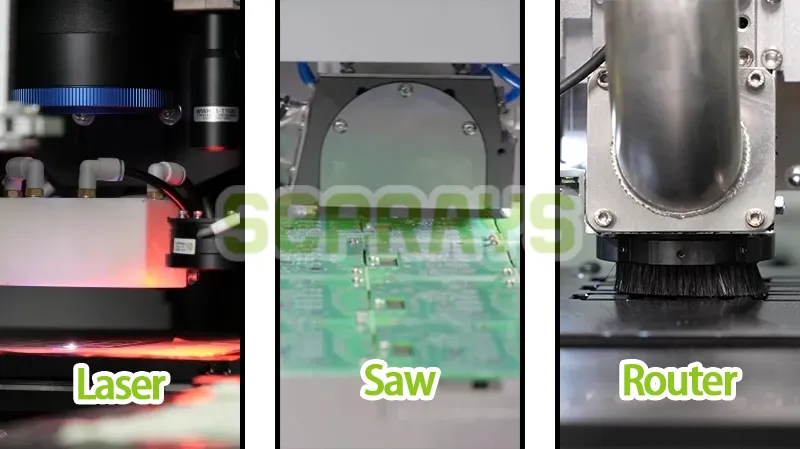
Laser processing could work, but the investment and process requirements may not be justified for the application.
Milling offers a middle ground: flexible mechanical cutting with a programmable path.
| PCB Requirement | Milling | V-Groove | Punching | Laser |
|---|---|---|---|---|
| Irregular outline | Excellent | Limited | Limited | Excellent |
| Straight V-groove | Possible | Excellent | Possible | Possible |
| Internal cutouts | Excellent | Poor | Depends on the die | Excellent |
| Product flexibility | High | Medium | Lower | High |
| Tooling requirement | Cutter | Blade/system | Custom die | Laser system |
| High-volume suitability | High | Very high | High | High |
| Process cost | Medium | Low–Medium | Medium | Higher in many cases |
This is not a universal ranking. The actual economics depend on the PCB, production volume, and quality requirements.
🧩 What About Sensitive Components?
This is where the discussion becomes more interesting.
A common assumption is that mechanical cutting automatically means high stress.
That is too broad.
A properly designed milling process can control cutting conditions, support the PCB correctly, and avoid unnecessary bending or impact. Seprays reports low-stress milling performance on its depaneling systems, but actual stress levels should always be validated with the customer’s own PCB and process conditions.
For boards containing fine-pitch ICs, BGA packages, MLCCs, optical components, or edge-sensitive devices, testing should include more than visual inspection.
Where possible, manufacturers should evaluate:
- Board deformation
- Solder-joint condition
- Component displacement
- Cutting-edge quality
- Electrical performance after separation
- Long-term reliability requirements
A board can look perfect immediately after cutting and still deserve further reliability testing.
💰 What Does Milling Really Cost?
The machine quotation is only one part of the calculation.
Consider:
Equipment + cutters + dust collection + labor + maintenance + downtime + scrap
Tool consumption deserves particular attention.
A very aggressive cutting parameter may shorten cycle time but increase cutter wear. A slower setting may increase cycle time while improving tool life and edge quality.
So the cheapest cycle is not necessarily the cheapest process.
For high-value electronics, the calculation becomes even more interesting.
Suppose a factory saves a small amount of processing cost per board but increases the risk of damaging an expensive assembled PCB.
That is not really a saving.
The counterintuitive conclusion: the best depaneling process is often the one that minimizes total production risk, not the one with the lowest cutting cost.
🏭 A Practical Semiconductor Manufacturing Example
Consider an overseas semiconductor equipment manufacturer producing several types of control PCBAs.
One product uses a relatively simple rectangular outline. Another has multiple internal cutouts and components close to the edge.
At first, the engineering team considered using the same separation process for both products.
After testing, the team found that a single method created compromises.
The simpler board could use a faster, more standardized process. The more complex board benefited from programmable routing.
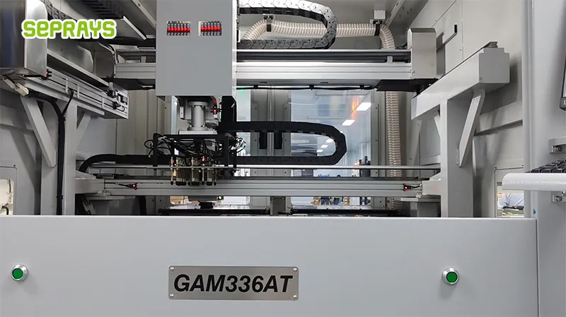
A Seprays milling solution was included in the evaluation because the company’s equipment portfolio covers applications ranging from offline routing to automated in-line depaneling.
The lesson is practical:
One factory does not necessarily need one depaneling technology.
Different PCB families can justify different processes.
This is increasingly relevant in 2026 as manufacturers deal with higher PCB density, shorter product cycles, and greater automation requirements.
🆚 When Should You Choose Something Else?
Milling is flexible, but it is not the answer to every application.
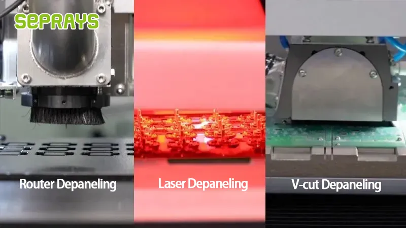
- Consider V-groove separation when the PCB already has straight, well-defined V-grooves and the production volume is high.
- Consider punching when the PCB geometry and production volume justify dedicated tooling.
- Consider laser when the application demands extremely controlled, non-contact processing or involves particularly sensitive structures.
In some factories, the most practical solution is a combination.
For example:
Router for complex boards + V-groove for standard products + laser for sensitive applications
This hybrid strategy can be more economical than forcing every product through one technology. Seprays also notes this application-matching approach in its recent depaneling guidance.
🧪 What Should You Test Before Buying?
Do not stop at a demonstration video.
Send representative production panels and ask the supplier to test them.
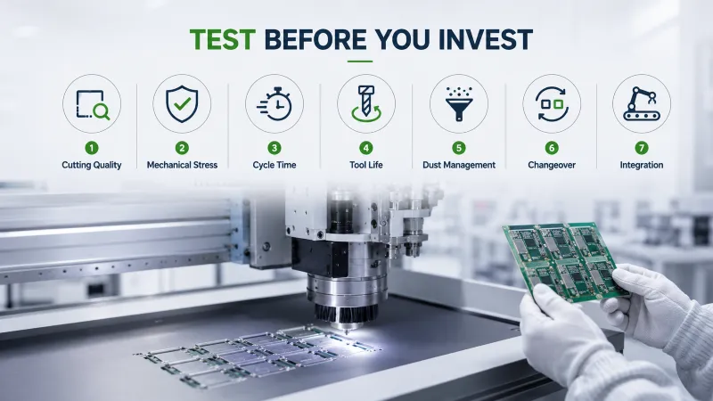
A useful evaluation should include:
1. Cutting quality
Check burrs, chipping, edge roughness, and dimensional accuracy.
2. Mechanical stress
Look beyond visible damage.
3. Cycle time
Measure the complete process, including loading and unloading.
4. Tool life
Check how cutter wear changes over repeated cycles.
5. Dust management
Confirm that extraction is appropriate for your production environment.
6. Changeover
Test how quickly the system can move between different PCB programs.
7. Integration
For automated factories, check communication with conveyors, loaders, unloaders, and MES systems.
A machine that performs well for ten boards may behave differently after several thousand cycles.
That is why production validation matters.
🧠 A Simple Decision Rule
If you are unsure whether milling is appropriate, start with these five questions:
| Question | If the answer is “Yes” |
|---|---|
| Does the PCB have an irregular outline? | Consider milling |
| Are there internal cutouts? | Consider milling |
| Do different products need different cutting paths? | Milling offers flexibility |
| Is production volume high? | Evaluate automation |
| Is the PCB highly sensitive? | Test milling stress and compare alternatives |
Do not choose milling simply because it is technically capable.
Choose it when its flexibility solves a real manufacturing problem.
🌍 Why Choose Seprays Group?
Seprays Group has been dedicated to PCB/FPC depaneling technology for more than 30 years, having been founded in Taiwan in 1993. Today, the company provides a broad range of solutions, including milling-cutter depanelers, laser depanelers, V-groove depanelers, punching depanelers, and automated loading, unloading, and handling systems.
Seprays’ equipment has been trusted by leading manufacturers and organizations, including Foxconn, Flextronics, State Grid, Luxshare, Compal, Wistron, China Electronics, Quanta, CRRC, China Aerospace, OPPO, ZTE, and Bosch. Its depaneling equipment and complete production solutions are used in factories across China and worldwide.
With more than three decades of experience, Seprays focuses on matching the depaneling process to the actual PCB rather than recommending the same technology for every application.
If you are evaluating milling, V-groove, laser, or another separation method, contact Seprays Group and share your PCB drawing, material, thickness, panel structure, and production volume for a practical application evaluation.
WhatsApp: +8618929266433
Электронная почта: sales@seprays.com
❓ FAQ
1. What is PCB milling used for?
It is used to separate individual PCBs from a panel by following a programmed cutting path with a rotating milling cutter. It is particularly useful for irregular outlines and internal cutouts.
2. Is milling better than V-groove depaneling?
Not always. Milling offers greater flexibility for complex PCB shapes, while V-groove can be more efficient for straight, pre-scored separation in high-volume production.
3. Can milling damage PCB components?
Any mechanical depaneling process must be properly controlled. Fixture design, cutting parameters, tool condition, and PCB structure all affect stress. Sensitive products should be tested using representative samples.
4. Is PCB milling suitable for high-volume manufacturing?
Yes. Automated milling systems can support high-volume production, especially when complex PCB geometry requires programmable cutting. The complete cycle time and automation level should be evaluated.
5. How do I know whether milling is suitable for my PCB?
Start with the PCB outline, internal cutouts, thickness, material, component clearance, required edge quality, and production volume. A sample test using your actual panel is the most reliable way to confirm suitability.