Russian
 English
 Spanish
 Japanese
 Korean
 Chinese
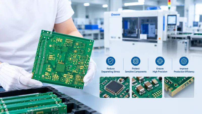
PCB depaneling stress is easy to overlook until a production line starts seeing cracked ceramic capacitors, unstable solder joints, or unexplained failures during reliability testing. For manufacturers producing compact, high-density electronic assemblies, separating boards is not just a cutting operation. It is part of quality control.
The challenge becomes more serious when components sit close to the board edge. A small amount of bending or vibration can create problems that are difficult to detect during routine inspection.
🔍 1. Which Components Are Most at Risk?
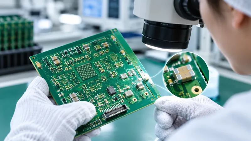
Not every component responds to separation forces in the same way. Multilayer ceramic capacitors (MLCCs), fine-pitch packages, BGAs, and heavy connectors deserve particular attention.
Common warning signs include:
- Ceramic capacitor cracks near the separation line.
- Solder joint damage that appears after thermal cycling.
- Board-edge chipping or deformation.
- Intermittent electrical failures that are difficult to reproduce.
The damage may not appear immediately after depaneling. A board can pass an initial electrical test and still develop a reliability issue later.
🛠️ 2. Choose the Depaneling Method Before Problems Occur
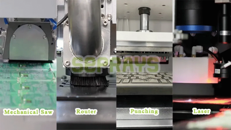
The right process depends on PCB material, outline, component clearance, and production volume. No single machine is ideal for every assembly.
| Method | Main advantage | Potential concern |
|---|---|---|
| V-cut separation | Efficient for straight-line panels | Breaking force can bend the board |
| Router depaneling | Flexible cutting paths and controlled separation | Tool vibration, wear, and dust |
| Laser depaneling | No direct mechanical cutting contact | Heat effects, material compatibility, and cost |
| Punching | Fast for stable, repeated designs | Local impact and dedicated tooling requirements |
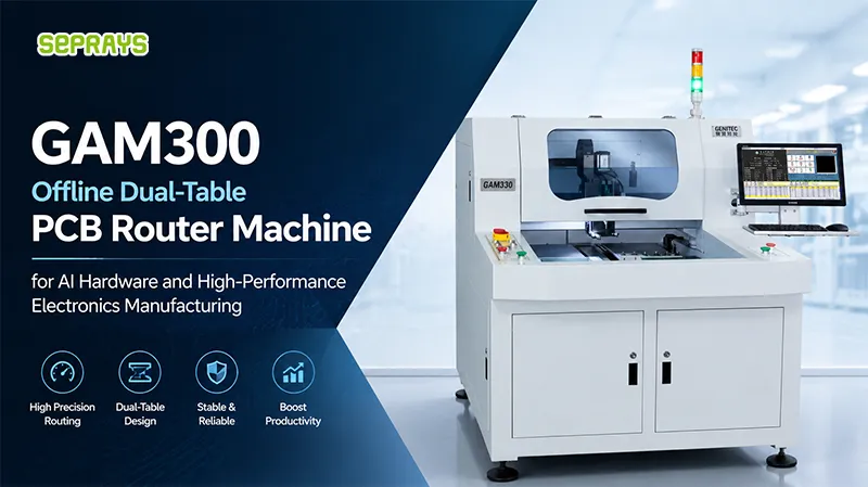
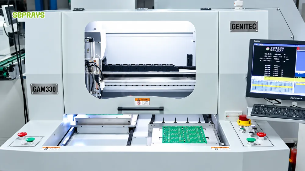
For irregular boards with sensitive components, a properly supported router may be a practical choice. For thin, flexible, or highly stress-sensitive assemblies, laser processing may deserve closer evaluation.
However, non-contact cutting does not automatically guarantee a defect-free result. Thermal effects, edge quality, and material response still need validation.
⚙️ 3. Five Practical Ways to Reduce Stress
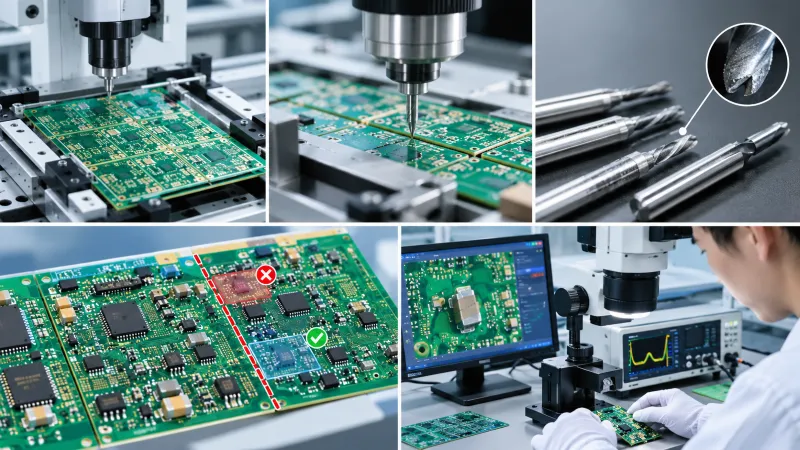
First, improve fixture support. The PCB should remain stable throughout cutting. Unsupported areas can flex when the cutter engages or when the final connection is released.
Second, review the cutting path. Avoid unnecessary movement near fragile components. For tab-routed boards, evaluate the order in which tabs are removed and how much support remains after each cut.
Third, monitor tool condition. A worn or damaged router bit can increase cutting resistance, vibration, and edge defects. Tool-life records and regular inspections help identify changes before they affect production.
Fourth, review component placement. Keep sensitive components away from separation lines where the design allows. Component orientation can also influence the strain experienced by ceramic parts. Follow the component manufacturer’s guidance rather than relying on one clearance value for every PCB.
Fifth, measure instead of guessing. For high-reliability products, use strain measurement where appropriate and inspect samples under magnification. Compare results across different fixtures, cutting speeds, tool conditions, and board designs.
💰 4. Why the Lowest Machine Price May Cost More
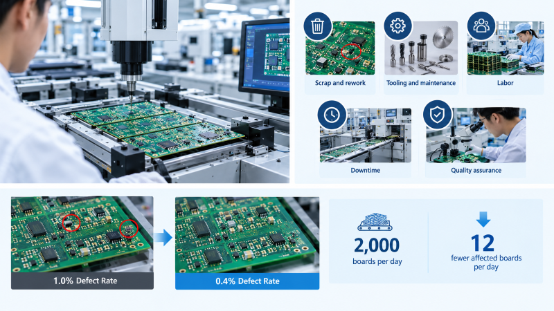
A depaneling machine should be evaluated by its total production cost, not its purchase price alone.
| Cost factor | What to evaluate |
|---|---|
| Scrap and rework | Defects caused by separation |
| Tooling and maintenance | Router bits, blades, fixtures, and replacement intervals |
| Labor | Manual handling, inspection, and rework time |
| Downtime | Tool changes, cleaning, and process adjustments |
| Quality assurance | Strain testing and reliability inspection |
For example, suppose a line processes 2,000 boards per day, and its depaneling-related defect rate falls from 1% to 0.4%. That represents 12 fewer affected boards per day.
This is an illustrative calculation, not a guaranteed improvement. The actual financial benefit depends on defect attribution, repair cost, production volume, and whether the process change creates other costs.
🏭 5. An Example from Semiconductor-Related Electronics Production
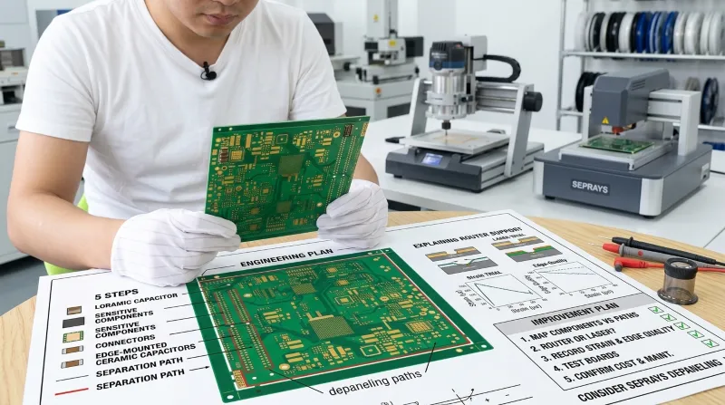
Consider an overseas manufacturer producing control boards for semiconductor-related equipment. Some assemblies contain ceramic capacitors and connectors close to the board edge.
The production team notices occasional edge damage and inconsistent inspection results after separation. Instead of immediately purchasing a faster machine, the team reviews the panel layout, fixture support, cutting sequence, and tool condition.
A practical improvement plan would include:
- Mapping sensitive components against each separation path.
- Comparing the existing process with a properly supported router or a laser trial where appropriate.
- Recording strain and edge-quality results under comparable conditions.
- Checking sample boards through electrical and reliability tests.
- Confirming cycle time, maintenance needs, and total cost before changing the production process.
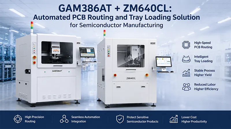
Seprays Group could be considered when evaluating suitable depaneling equipment for this type of application. The final selection should depend on the actual PCB drawings, component locations, material, and acceptance criteria.
This is an illustrative manufacturing scenario, not a claim of a documented customer installation or measured improvement.
🧪 6. An Important Lesson: Faster Is Not Always Better
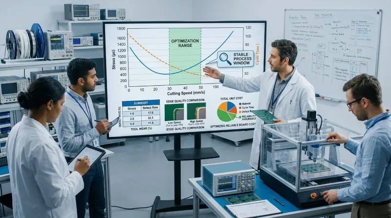
Increasing cutting speed may improve cycle time, but it can also change vibration, cutting forces, or edge quality. Reducing speed alone does not guarantee lower stress either.
The better approach is to establish a stable process window. Test representative boards, record the results, and confirm that quality remains consistent across tool wear, product changeovers, and normal production variation.
A useful question for engineering teams is: Are we optimizing the cutting cycle, or are we optimizing the cost of producing a reliable board?
The two goals should support each other.
🌐 7. Why Choose Seprays Group?
Seprays Group has been dedicated to PCB/FPC depaneling technology for more than 30 years, providing a broad range of solutions, including milling-cutter depanelers, laser depanelers, V-groove depanelers, punching depanelers, and automated handling systems.
Its equipment is trusted by leading manufacturers, including Foxconn, Flextronics, State Grid, Luxshare, Compal, Wistron, China Electronics, Quanta, CRRC, China Aerospace, OPPO, ZTE, and Bosch. Seprays equipment is used in factories across China and worldwide.
For manufacturers working with sensitive components, equipment selection should start with the real production challenge—not simply the advertised cutting speed. The PCB geometry, required precision, stress limits, dust-control needs, and automation requirements all matter.
If you are experiencing board damage or inconsistent depaneling quality, please contact Seprays Group to discuss your application and evaluate a suitable solution.
WhatsApp: +8618929266433
Электронная почта: sales@seprays.com
❓ FAQ
1. What causes stress during PCB depaneling?
Board bending, cutting forces, vibration, unsupported areas, and excessive separation force can all contribute.
2. Which depaneling method creates the least mechanical stress?
Laser cutting avoids direct mechanical contact, but thermal effects must still be assessed. Properly supported routing can also achieve low stress for suitable PCB designs.
3. How far should sensitive components be from the cutting line?
There is no universal clearance for every component and process. Follow component-manufacturer recommendations and validate the actual panel design.
4. Can a PCB pass electrical testing but still have depaneling damage?
Yes. Some cracks or solder-joint defects may not cause an immediate electrical failure. Additional inspection or reliability testing may be necessary.
5. How can manufacturers verify that a new process is safer?
Compare strain measurements where appropriate, inspect cut edges, perform electrical testing, and run relevant reliability tests using representative production boards.